Display Backlighting Repair
I have an old 2003 Nissan car. The light on the clock/radio never worked from purchase (also the shifter light). The original lights used to light the front panel of the radio were of an incandescent type and soldered surface-mount to the PCB, really annoying. I decided on replacing the lights with surface-mount LEDs. The front panel lights are powered from the car itself, not from the radio.

Pin “C” is the illumination power (12V). Pin “I” is the illumination control. This pin varies from 0V to 12V depending on the adjustment of the brightness potentiometer. This changes the differential voltage of the bulbs, leading to varying brightness.
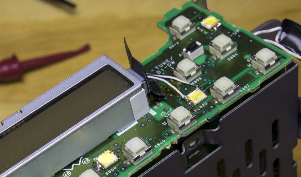
I had to decide where I wanted the current limiting resistor to be located – one resistor at every led or one for all LEDs. I decided on putting all the LEDs in parallel and having one resistor for the whole set. This allowed easier soldering since I could drop-in replace the bulbs without needing to solder a resistor at every led. A downside to this arrangement is that the LEDs could see different currents due to varying forward voltages. The LEDs that lit the display were on a different circuit than the car-powered LEDs. The circuit was non-functional, so I bypassed it and soldered the display LEDs to the car-powered circuit.
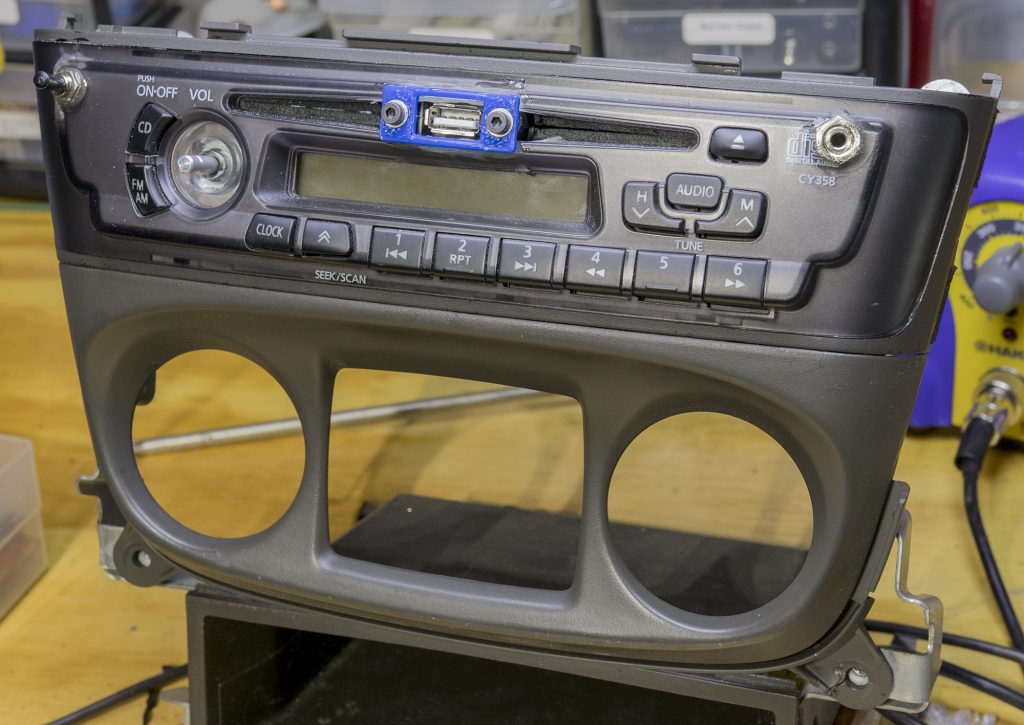
Adding an Auxiliary Port
Since I had the radio open, I might as well add an aux port and a USB charging port. I first removed the CD player because it did not work at all. It released magic smoke at one point in the front panel repair. The radio seems to work fine without the CD mechanism. This allowed me the space to fit a 12V to 5V DC-DC converter inside the housing.
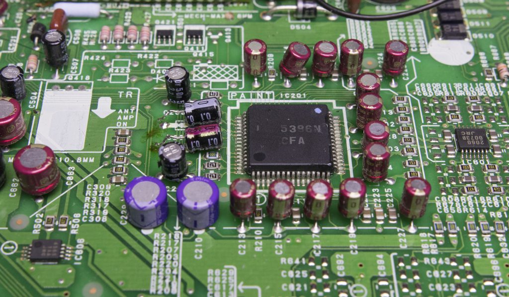
I first found the volume and tone IC (LC75386N) and found the pins that accept an analog audio signal. One pair had to be the CD player, the other set, the AM/FM radio. Pins 49-64 in the IC accepted an audio signal.
Then I used an external audio source and touched the wires to the negative end of the input dc-blocking capacitors. I listened for an output on the speaker which I had soldered to the output. I found the left and right channel of the AM/FM radio by this method.
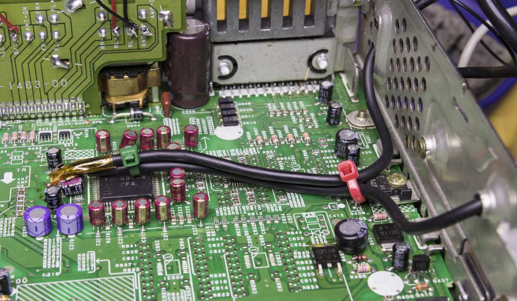
I then soldered wires to a DPDT switch. The center going to the input of the audio IC. One side going to the AM/FM radio and the other going to an aux input. When the switch is switched, it selects between the radio and the aux input.
Completed Build
I added a USB charging port to the radio from Car Power Technology. It is rated for 3A at 5V but I could only get about 1.5A out of it. Still, this is more than sufficient to charge a cellphone. The AM/FM or Aux selector switch is on the left while the Aux input is on the right.