Overview
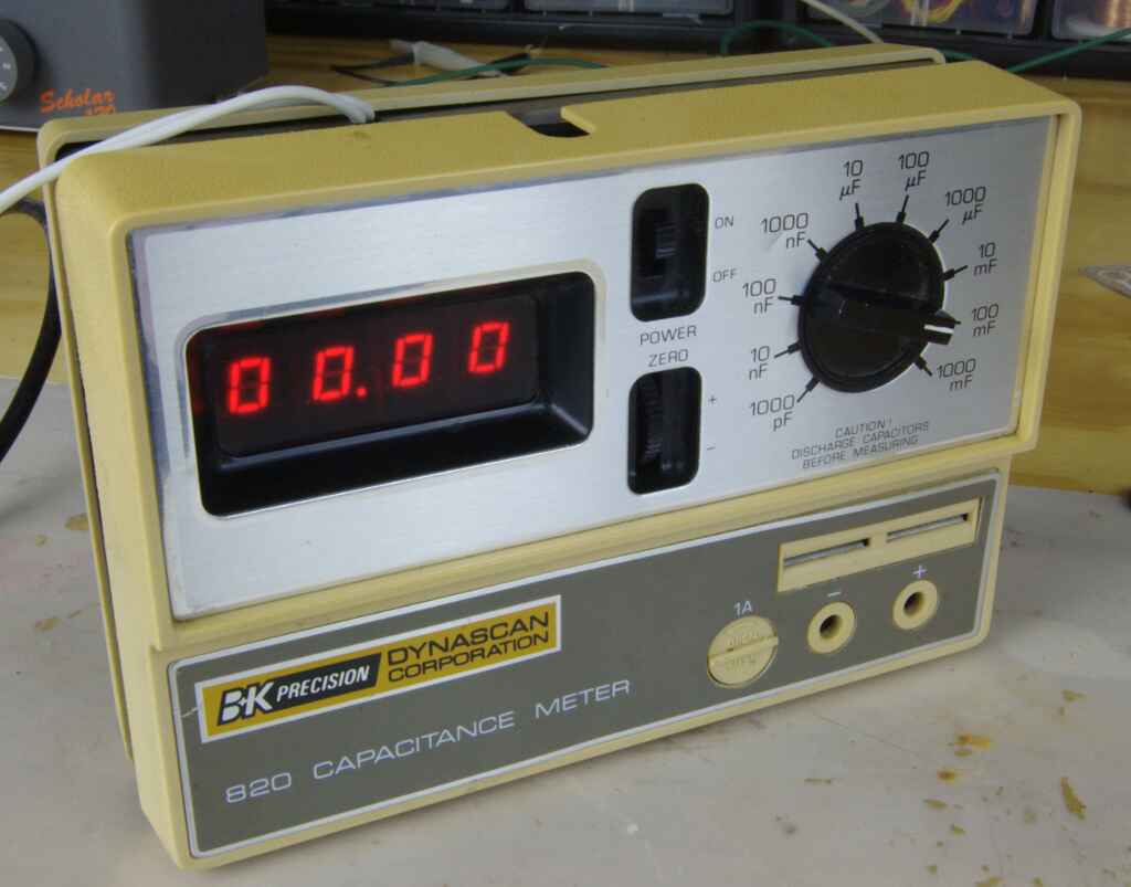
The BK Precision 820 capacitance meter measures capacitor values. A range selection switch selects the various ranges of the meter from 1000pF to 1F full-scale. The user-guide/service manual can be found here. This manual features a full schematic and block diagram of the unit.
The meter has a zero potentiometer which can zero the lower ranges to null the stray capacitance of the wires, and terminals of the meter itself. A 1A fuse is conveniently placed on the front panel to protect against charged capacitors being connected. This model features dual terminals, where the capacitor can be inserted directly and banana jacks for larger capacitors or short leads. The display is comprised of 4 7-segment led displays.
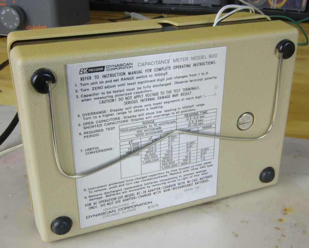
On the back, there is an instruction guide and a handy capacitor conversion chart. There is also a copyright date of 1978 on the back. A tilting bale props the meter up on the bench surprisingly well, no tipping over or side to side movement.
Teardown
The repair starts by taking the back cover revealing the battery housing and terminals. I already have done the mod in this picture. The unit has space for 4 C cell batteries which I have bypassed with the mod. A much more elegant approach would have been to put the voltage regulator in series with the switch and use the 3.5mm jack at the top of the unit to power the device.
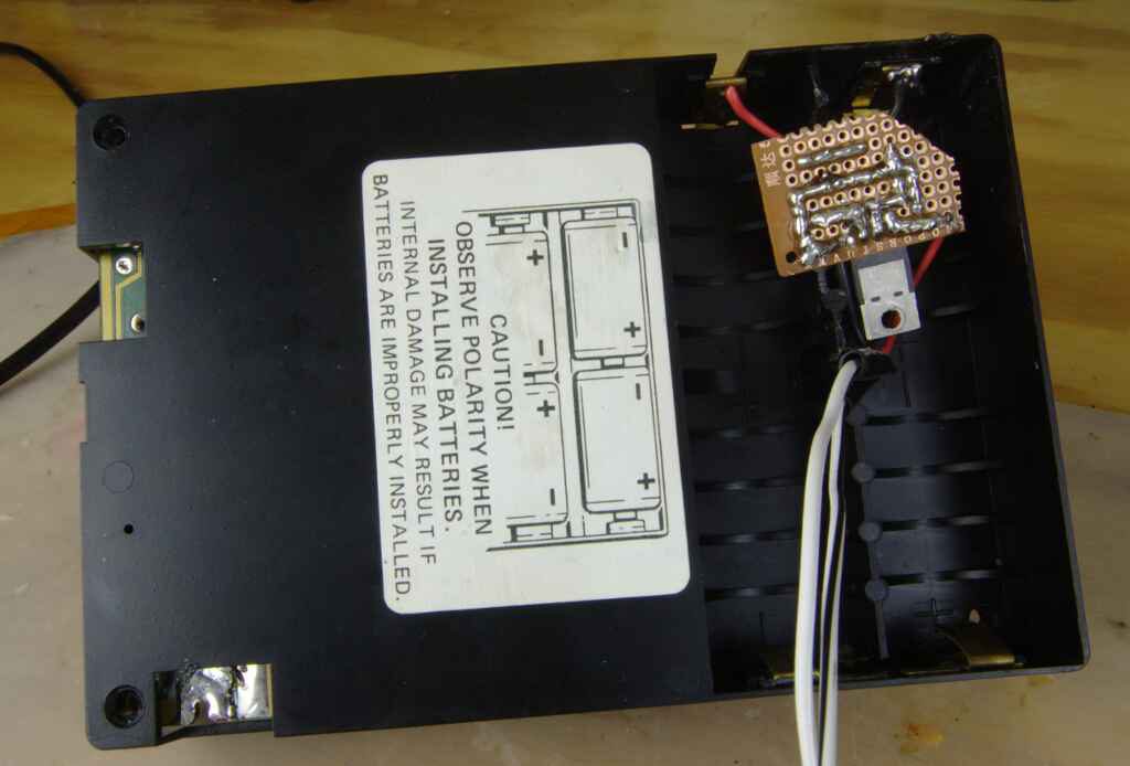
I take the front cover off by de-soldering the positive terminal of the front panel and removing 4 phillips screws.
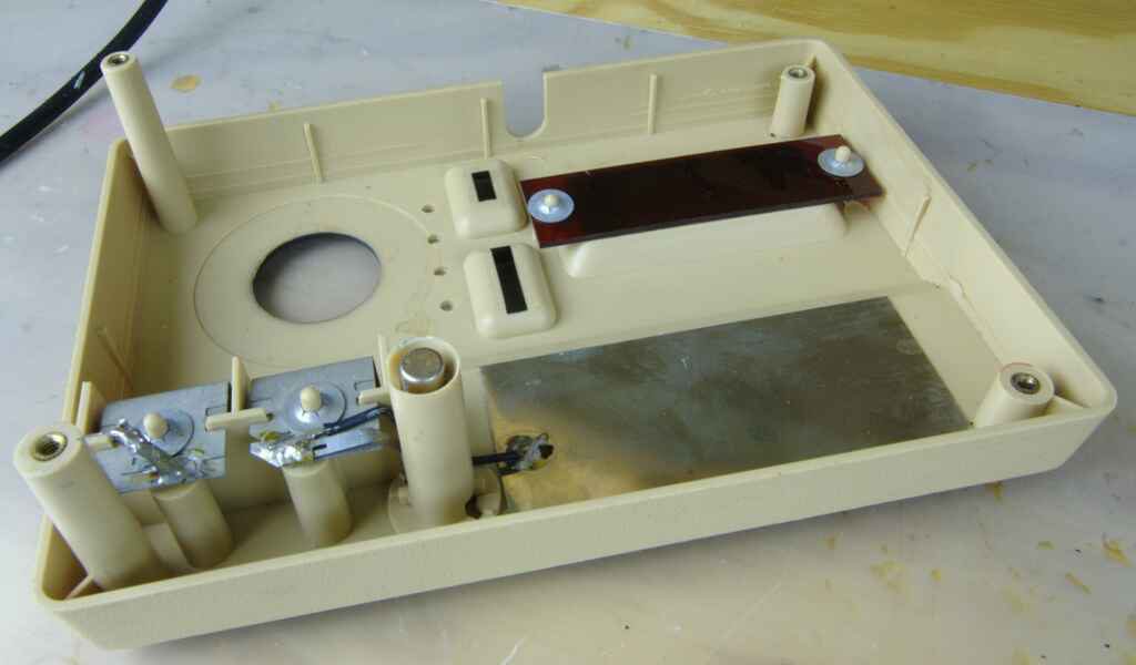
The inside of the front cover has an integrated fuse holder which press fits onto the main circuit board. There is a tab which comes off the negative terminal and contacts the fuse. There is also a red tinted window which improves the contrast of the led segments within.
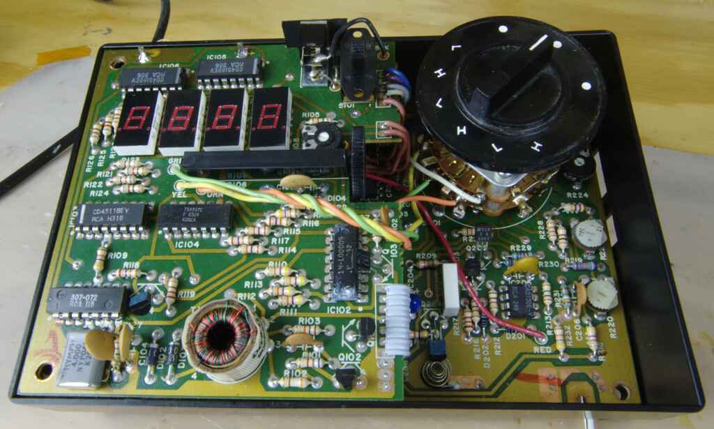
The circuitry in this unit is dated to 1983 according to the date code on one of the ICs. There are about 9 ICs on this device with some hidden under the top board.
There is a nice transformer with multicolor windings on the bottom left of the picture.This is part of the simple boost converter that boosts the voltage from 4.5-6V to 13-18V
The main clock crystal is situated close by providing a 4MHz clock which is used for capacitance measuring. The 1000pF range uses the 4MHz clock directly, while the other ranges divide it down. The zeroing potentiometer is a ~50 turn 100k pot which feels really smooth and can be turned for along time.The spring providing contact to the 1A fuse can be seen in the lower portion of the picture.
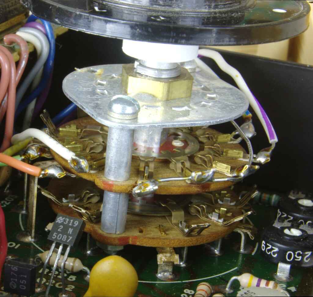
The large range selector switch has gold plated contacts and feels OK but it could have more of a snap action when turning.
Repair
A 6V voltage source was soldered across the battery terminals and turned on. The meter’s led digits lit up displaying 00.00, a good sign. After looking closely at the battery terminal contacts, A large deposit of corrosion was present on the negative lead. This was determined to be the failure.
Modification
The battery life of this unit is very poor. It only lasts 6 hours with 4 C cell batteries. Although I won’t be using this unit every day, the inconvenience of having the batteries run out while experimenting is too great. I made a simple LM317 Voltage regulator which outputs ~5.8V to mimic fresh batteries. I could of also just plugged a 5-6v charger into the port at the top. Although then I would run into the problem of finding the right plug pack that fits the unit.
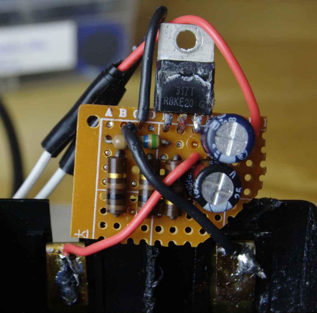
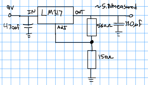
I used this site to find the required resistor values for the circuit.
After measuring many types of capacitors, the capacitor meter seems to function and display the correct value. It measures much faster than my cheap (~$20) multimeter and has a larger range.
Theory of Operation
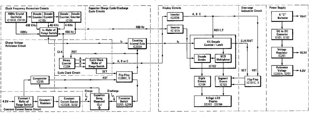
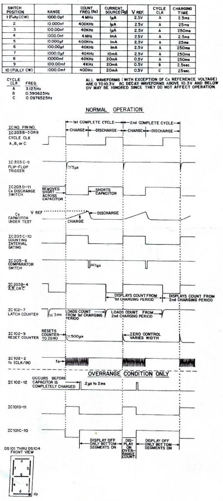
An in-depth analysis of the circuit is written in the datasheet page 8. Describing this block diagram. The meter uses the simple RC time constant principle to determine the capacitance.
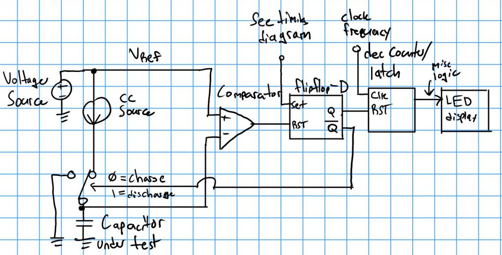
A simplified circuit diagram is made to illustrate how the meter determines the capacitance. The range selection dial selects the frequency, comparator voltage, charge current, and charge resistance (see timing diagram).
The constant current source charges the capacitor until it reaches the comparator threshold. While this is happening the counter is incrementing based on the selected clock frequency.When the capacitor reaches the reference voltage, it resets the flipflop which does two things, discharging the capacitor and resetting the counter. The capacitor discharging is accomplished by shorting the charged side of the capacitor to ground using an NPN transistor.
When the counter is reset, the value of its count is displayed on the screen. A delay is started to make sure that the capacitor is fully discharged. When the delay is over the flipflop is set again restarting the measurement. When the next measurement is performed, the new value is latched to the led display.
Awesome write up! Thanks from 10 years in the future!! I have an old one and funny but somehiw I went to the darn web before I bothered to actually read the ibstructions on the back of the cover!! Looking to zero the unit and… well…. Nvm…(Roseanne, Rosanna Danna) 🤭